Introduction
Testing devices such as transistors, DC-DC converters, engine control modules (ECMs), or LED/photodetector systems typically requires test systems configured from multiple instruments. The common challenge with these applications is the difficulty of triggering and acquiring measurements at exactly the same time or in a specific sequence. Test system triggering is especially challenging when high throughput or precise timing is critical.
Integrating multiple instruments into an efficient test system poses many interesting problems. For example, seamless system integration typically implies a need for speed or increased throughput. In addition to speed, other issues to consider include measurement accuracy at a specific speed and precise timing of the measurement sequence.
This note discusses how to configure a few common test system solutions using two and three instruments. While it isn’t intended to be an exhaustive study of instrument synchronization methods, it illustrates and offers an analysis of common practices.
Test System Description
Instrument Triggering
It is common for test instrumentation to support input and output triggers to control the measurement sequence. Figure 1 illustrates the most common form of input and output triggering. Here, an input trigger signals the meter to begin the operation (for example, acquire data, close a switch channel, etc.) After the operation is complete, the meter sends an output trigger to the rest of the system.

Figure 1. Typical instrument trigger input/output scheme.
The instruments in Keithley’s Series 2400 SourceMeter line support a triggering scheme that’s much more complex than that shown in Figure 1. The SourceMeter instrument’s measurement and triggering sequence is governed by what is called the Trigger Model. The Trigger Model is simply a flow chart that represents how the measurement sequence, input/ output triggers, and even counters relate to each other. Figure 2 is a simplified version of the SourceMeter Trigger Model. Once the SourceMeter instrument is told to exit the Idle Layer with the “INIT” command, the Trigger Model governs the instrument’s operating sequence. The SourceMeter instrument won’t respond to any bus commands or front panel operations while the Trigger Model is initialized.
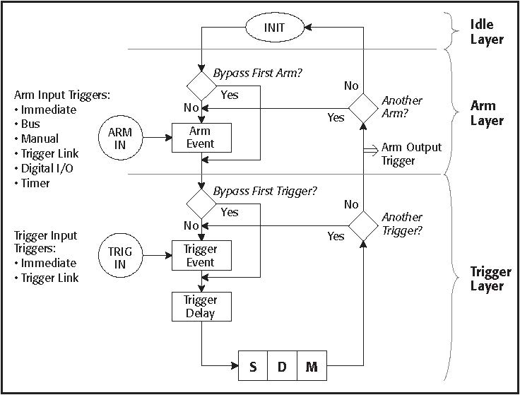
Figure 2. Representation of Trigger Model flowchart for SourceMeter instruments.
The source-delay-measure (SDM) cycle is a subset of the Trigger Model shown in Figure 2. The SDM cycle implies that the source is turned on, a programmable delay is executed, then the measurement (analog-to-digital conversion) is performed. The SourceMeter instrument allows the user to trigger the beginning of each of these steps or the instrument can output a trigger after each of these steps. Figure 3 illustrates the SDM cycle and triggering. For a more detailed representation, see Figure 6.
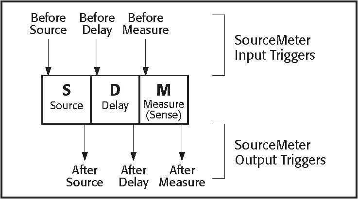
Figure 3. SourceMeter trigger input/output configuration.
The flexibility of the input and output triggers shown in Figure 3 makes possible the example applications described in this note. Each example illustrates how the SDM cycle of each instrument in the system is configured to work in synch with the others.
When another instrument or controller is triggering a SourceMeter instrument, it may inadvertently receive and latch input triggers that should not be executed. Inadvertent triggers can affect proper system synchronization. Sending the bus command “TRIG:CLE” to any SourceMeter instrument with firmware revision C13 or higher will clear any pending or latched triggers immediately. This command should be sent after the instrument is reset. Other instruments from Keithley do not latch Trigger Link input triggers.
Methods and Techniques
Trigger Link
The test systems presented could not be tightly integrated without Trigger Link, a standard feature on all newer Keithley products. The Trigger Link bus is used by the instrumentation to handshake each other through test sequences.
The Trigger Link bus has specific electrical and timing characteristics that require compatible equipment. All models and examples discussed in this note are compatible with the Trigger Link bus. Figure 4 illustrates the input and output pulse specifications.
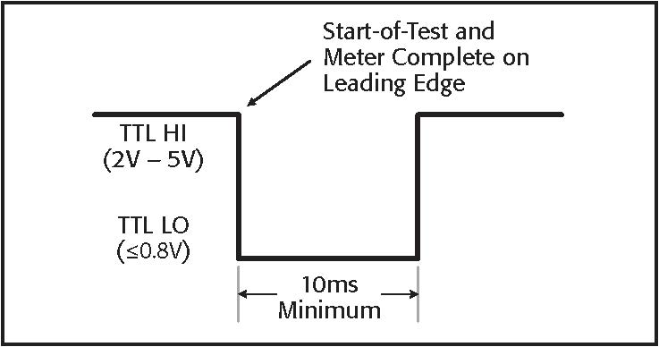
Figure 4. Trigger Link pulse characteristics.
Figure 5 shows a simple way to increase the drive current of the Trigger Link output current. There is no defined limit on the number of instruments that can be connected in parallel. To help ensure the distributed signal has sufficient strength when more than four instruments must be triggered simultaneously, Keithley recommends using this circuit, which is simply two TTL AND gates with all inputs and outputs tied together.
Source Memory Sweep and Synchronization
A built-in automatic test sequencing algorithm known as Source Memory Sweeping is another feature unique to the SourceMeter family. It allows the user to pre-program a test sequence into the instrument, then execute the test sequence with one initiation
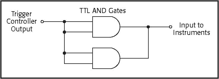
Figure 5. SDM triggers to synchronize three SourceMeter instruments.
command. Each test point within the sequence is highly configurable. One test could output voltage, measure resistance, and perform pass/fail analysis on the result, while the next could output current and not take any measurement without analysis. Since these tests are saved in memory, they must be recalled from memory to reconfigure the instrument during the test sequence. This process is detailed in Figure 6.
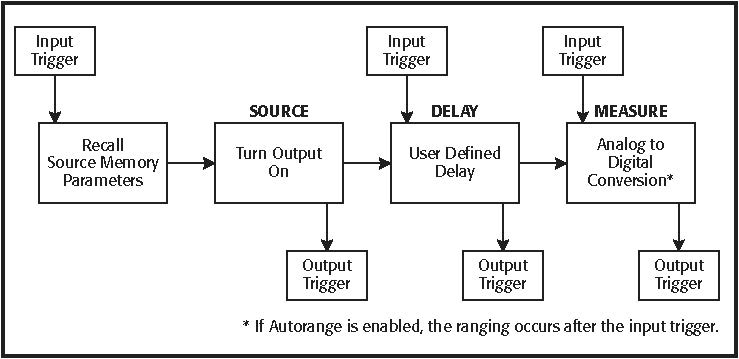
Figure 6. SDM sequence with Source Memory parameter recall.
If the SourceMeter instruments all have the same firmware and are programmed with the same test parameters, the execution times for each step should be the same. Time variation is largely due to the Source Memory recall and auto-ranging steps. These two steps take an indeterminate amount of extra time. Given that the timing is indeterminate, the instruments must be triggered so that the important step (i.e., the measurement) occurs at the same time for multiple instruments. Table 1 shows some typical times for various Source Memory recall functions.
Table 1. Parameter change execution time.
|
Description |
Approximate Execution Time (ms) |
|
Changing current range |
5 |
|
Changing voltage range |
5 |
|
Switching from I source to V source* |
11 (worst case) |
* Switching source mode requires that the output be turned off and often requires changing both the voltage and current ranges.
As the timing numbers in Table 1 indicate, during a Source Memory sweep, the SDM cycle time may vary significantly. This variation is known as timing “jitter.” If three instruments receive the same trigger, all three may turn on their sources and take measurements at different times. Figure 7 illustrates the timing variation.
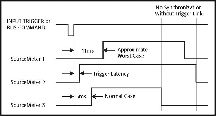
Figure 7. Example timing variation between different instruments.
Given an understanding of the issues associated with the SDM cycle and sources of timing jitter, the question becomes how to synchronize everything. By using the triggers shown in Figure 3, the SourceMeter instruments can be configured to take their measurements at the same time.
All of the input trigger lines for each instrument should be tied together so that each receives the trigger at the same time. Each output line should be separate and accounted for separately. The process works like this:
1. The trigger controller outputs a trigger that is received by all instruments (source input).
2. A Source Memory locations is recalled from memory.
3. The source output is enabled on all instruments.
4. Each instrument performs the user-defined delay.
5. Each instrument outputs a trigger to the controller once the delay operation is complete.
6. The trigger controller waits for a trigger output from each instrument (delay output).
7. The trigger controller outputs a trigger that is received by all instruments (measure input).
8. Each instrument begins the measurement operation.
9. Each instrument outputs a trigger to the controller once the measurement is complete.
10. The trigger controller waits for a trigger output from each instrument (measure output).
11. Go to Step 1 to begin the next test.
Figure 8 shows the result of synchronization of the triggering. The measurement falling edges for all the SourceMeter instruments can line up exactly if auto range is disabled, integration rate is the same, concurrent measurement status is the same, and the state of auto zero is the same for all meters.
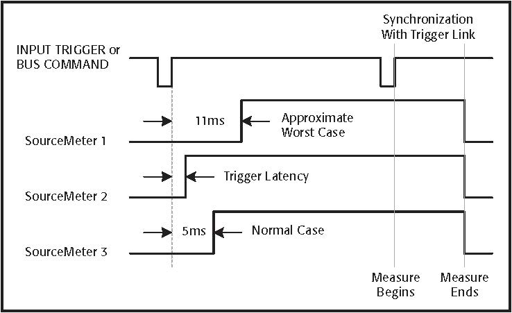
Figure 8. Effect of trigger synchronization.
Example Application #1 (Two Instruments)
Figure 9 illustrates the LED with photodetector (PD) system.
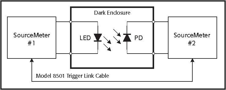
Figure 9. Basic LED/Photodetector System configuration.
The objective of the system is to supply a positive current bias to the LED using SourceMeter #1 in such a way that the LED emits light. SourceMeter #2 provides a negative voltage bias to the PD and measures the resulting leakage current. The SourceMeter instruments are capable of sourcing either voltage or current while simultaneously reading back the source values (both voltage and current) with up to 5½ digits of resolution. (The full resolution is obtained while acquiring data at one line cycle integration rates.)
When light from the LED shines on the reverse-biased PD, the leakage current increases. In fact, the magnitude of the leakage current correlates to the intensity of the light striking the active region. Therefore, the light emitting capabilities of the LED can be characterized by careful measurement of the PD. For the data to be useful, it is desirable to make the voltage measurement on the LED and the current measurement on the PD at exactly the same time. Throughput is critical, so the dwell time of the source values are typically kept as short as possible.
To execute the test sequence steps properly, the two instruments must trigger each other over the Trigger Link bus (see the section titled “Trigger Link”). The Model 8501 Trigger Link cable connects the two instruments to enable the process.
The SCPI (Standard Commands for Programmable Instruments) Trigger Model defines the trigger sequence for the instruments, which is composed of input and output triggers, counters, and device actions. Configuring the Trigger Model properly will allow the system to work.
Two examples have been developed to illustrate the Trigger Model configuration for the dual SourceMeter system shown in Figure 9. The first shows a single-point test where the LED and PD are tested once. The second example shows how to configure a simple ten-point sweep with both instruments.
Configuring the Trigger Model
This code example illustrates the basic Trigger Model commands for performing a single-point test with two instruments acquiring their data at the same time. The “send2400_1” commands configure the meter to act as the master, while the other commands are intended to set the second meter to perform as a slave. In the next program example, the configuration commands are expanded and are intended specifically for either LED or PD measurements. (Pay special attention to the comments for each command.)
|
send2400_1 (“*RST”) |
‘ Reset SourceMeter #1 |
|
send2400_1 (“TRIG:CLE”) |
‘ Clear any pending input triggers |
|
send2400_1 (“ARM:DIR ACC”) |
‘ Wait for Arm event (IMM) |
|
send2400_1 (“ARM:COUN 1”) |
‘ Perform 1 scan |
|
send2400_1 (“ARM:SOUR IMM”) |
‘ Immediately go to next layer |
|
send2400_1 (“arm:outp none”) |
‘ No output triggers from scan |
|
send2400_1 (“TRIG:DIR ACC”) |
‘ Wait for trigger event (TLINK) |
|
send2400_1 (“TRIG:COUN 1”) |
‘ Perform 1 test |
|
send2400_1 (“TRIG:SOUR TLIN”) |
‘ Use Trigger Link for triggering |
|
send2400_1 (“TRIG:OUTP SOUR”) |
‘ Output trigger after source |
|
send2400_1 (“TRIG:INP SENS”) |
‘ Wait for trigger before measure |
|
send2400_1 (“TRIG:ILIN 1”) |
‘ Trigger Link input line |
|
send2400_1 (“TRIG:OLIN 2”) |
‘ Trigger Link output line |
|
send2400_2 (“*RST”) |
‘ Reset SourceMeter #2 |
|
send2400_2 (“TRIG:CLE”) |
‘ Clear any pending input triggers |
|
send2400_2 (“ARM:DIR ACC”) |
‘ Wait for Arm event (IMM) |
|
send2400_2 (“ARM:COUN 1”) |
‘ Perform 1 scan |
|
send2400_2 (“ARM:SOUR IMM”) |
‘ Immediately go to next layer |
|
send2400_2 (“arm:outp none”) |
‘ No output triggers from scan |
|
send2400_2 (“TRIG:DIR ACC”) |
‘ Wait for trigger event (TLINK) |
|
send2400_2 (“TRIG:COUN 1”) |
‘ Perform 1 test |
|
send2400_2 (“TRIG:SOUR TLIN”) |
‘ Use Trigger Link for triggering |
|
send2400_2 (“TRIG:OUTP DEL”) |
‘ Output trigger after delay |
|
send2400_2 (“TRIG:INP SOUR”) |
‘ Wait for trigger before source |
|
send2400_2 (“TRIG:ILIN 2”) |
‘ Trigger Link input line |
|
send2400_2 (“TRIG:OLIN 1”) |
‘ Trigger Link output line |
|
send2400_2 (“INIT”) |
‘ Initiate SourceMeter #2 |
|
send2400_1 (“INIT”) |
‘ Initiate SourceMeter #1 |
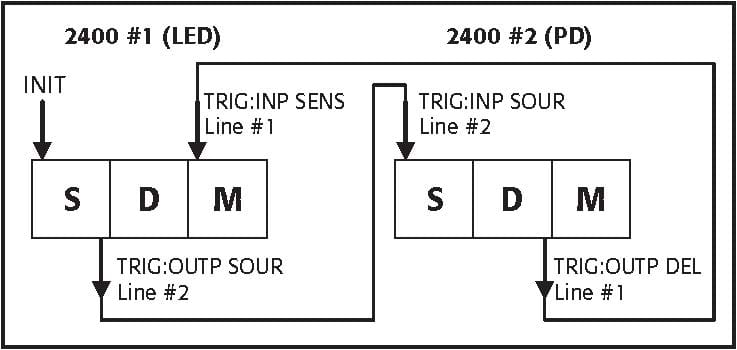
Figure 10. SDM triggers to synchronize two SourceMeter instruments.
The SDM cycle’s input and output triggers that were enabled in this code example are summarized in Figure 10. From the initial “INIT” command, the two instruments then trigger each other to complete their measurement operations at virtually the same time. The same triggering scheme is also carried out in the next section, “Programming and Running a Sweep.”
Programming and Running a Sweep
This section illustrates how to configure the SourceMeter #1 (LED) to perform a current sweep from 1 to 10mA in 1mA steps (ten test points). At each sweep point, the SourceMeter instrument will increase the source level, send an output trigger to SourceMeter #2 (PD), and wait for its measurement to be triggered. Once the PD SourceMeter instrument receives the trigger, it begins its measurement sequence. Immediately before the PD measurement begins, the PD SourceMeter instrument sends a trigger back to the LED SourceMeter instrument to ensure both measurements occur at the same time.
Send2400_LED (“*RST”) ‘ Reset instrument
Send2400_LED (“TRIG:CLE”) ‘ Clear any pending triggers
Send2400_LED (“SYST:azer oN”) ‘ Ensure auto zero is enabled
Send2400_LED (“form:elem volt”) ‘ Send only voltage readings to PC
Send2400_LED (“sour:cle:auto on”) ‘ Automatically turn output ON/OFF
Send2400_LED (“sour:cle:auto:mode tco”)
‘ Output off after trigger count
The following section configures the Trigger Model for the LED SourceMeter instrument.
Send2400_LED (“arm:coun 1”) ‘ Perform 1 sweep per “:INIT”
Send2400_LED (“arm:sour imm”) ‘ Immediately go to Trig layer
Send2400_LED (“arm:dir ACC”) ‘ Wait for trigger event (IMM)
Send2400_LED (“arm:outp none”) ‘ No output triggers from scan
Send2400_LED (“trig:coun 10”) ‘ Perform # points in sweep
Send2400_LED (“trig:sour tlin”) ‘ Trigger using Trigger Link
Send2400_LED (“trig:dir acc”) ‘ Skip first trigger
Send2400_LED (“trig:outp sour”) ‘ Output trigger after source “on”
Send2400_LED (“trig:inp sens”) ‘ Wait for trigger before measure
Send2400_LED (“trig:ilin 1”) ‘ Input trigger line
Send2400_LED (“trig:olin 2”) ‘ Output trigger line Send2400_LED (“trig:del 0”) ‘ Set trigger delay before source The following commands configure the measurement and voltage bias parameters for the SourceMeter instrument connected to the LED.
Send2400_LED (“sour:func curr”) ‘ Output constant current
Send2400_LED (“sens:func ‘volt’”) ‘ Measure forward voltage of LED
Send2400_LED (“sour:curr:star 0.001”)
‘ Start point for sweep
Send2400_LED (“sour:curr:stop 0.01”)
‘ Stop point for sweep
Send2400_LED (“sour:curr:step 0.001”)
‘ Define sweep step size
Send2400_LED (“sour:curr:rang 0.01”)
‘ Set fixed measurement range
Send2400_LED (“sour:del 0.001”) ‘ Set source delay before measure
Send2400_LED (“sens:volt:prot 2”) ‘ 2V compliance range
Send2400_LED (“sens:volt:rang 2”) ‘ Measure on 2V range
Send2400_LED (“sens:volt:nplc 1) ‘ Measurement integration
Send2400_LED (“sour:curr:mode swe”)
‘ Perform sweep function
The next section of code will configure the SourceMeter #2 (PD) to perform a current measurement for every sweep step of the SourceMeter #1 (LED). The LED SourceMeter instrument will output a current, then trigger the PD SourceMeter instrument to take its measurement. The PD SourceMeter instrument then triggers the LED SourceMeter instrument to signify it has completed its task.
Send2400_PD (“*rst”) ‘ Reset instrument
Send2400_PD (“trig:cle”) ‘ Clear any pending triggers
Send2400_PD (“syst:azer oN”) ‘ Ensure auto zero is enabled
Send2400_PD (“form:elem curr”) ‘ Send only current readings to PC
Send2400_PD (“sour:cle:auto on”) ‘ Automatically turn output ON/OFF
Send2400_PD (“sour:cle:auto:mode tco”)
‘ Turn off after trigger count
The following section configures the Trigger Model for the PD SourceMeter instrument.
|
Send2400_PD (“arm:coun 1”) |
‘ Perform only one scan |
|
Send2400_PD (“arm:sour imm”) |
‘ Immediately start scan |
|
Send2400_PD (“arm:dir acc”) |
‘ Wait for trigger event (IMM) |
|
Send2400_PD (“arm:outp none”) |
‘ No output triggers from scan |
|
Send2400_PD (“trig:coun 10”) |
‘ Perform # points in sweep |
|
Send2400_PD (“trig:sour tlin”) |
‘ Trigger using Trigger Link |
|
Send2400_PD (“trig:dir acc”) |
‘ Wait for first trigger |
|
Send2400_PD (“trig:inp sour”) |
‘ Wait for trig before source “on” |
|
Send2400_PD (“trig:outp del”) |
‘ Output trigger after delay |
|
Send2400_PD (“trig:ilin 2”) |
‘ Input trigger line |
|
Send2400_PD (“trig:olin 1”) |
‘ Output trigger line |
|
Send2400_PD (“trig:del 0”) |
‘ Set trigger delay before source |
The next commands configure the measurement and voltage bias parameters for the SourceMeter instrument connected to the PD.
Send2400_PD (“sour:func volt”) ‘ Output constant voltage
Send2400_PD (“sens:func ‘curr’”) ‘ Measure leakage current of PD
Send2400_PD (“sour:curr:rang:auto on”)
‘ Enable source auto range
Send2400_PD (“sour:volt 5”) ‘ Set output level
Send2400_PD (“sour:del 0.01”) ‘ Set source delay before measure
Send2400_PD (“sens:curr:prot 0.01”) ‘ 10mA compliance range
Send2400_PD (“sens:curr:rang 0.01”) ‘ Measure on 10mA range Send2400_PD (“sens:curr:nplc 1”) ‘ Measurement integration
The following commands are used to begin testing and enter the results into the PC via the GPIB bus. The data from this configuration would be in ASCII format, but the Series 2400 instruments are capable of sending binary (IEEE 754 single precision format) data to the PC to decrease overall test time.
Send2400_PD (“read?”) ‘ Initialize & ask for data
Send2400_LED (“read?”) ‘ Initialize & ask for data
Enter2400_LED(LED_Data) ‘ Enter LED Data into string Enter2400_PD(PD_Data) ‘ Enter PD Data into string Example Application #2 (Three Instruments)
System integration becomes increasingly challenging when three instruments are used. Figure 11 shows a device where an LED and a PD are integrated into the same device. A second PD is installed in the test fixture to verify the performance of the integrated device independently. For this application, SourceMeter #1 powers the LED and the other two meters each measure a photodetector. This is the same analog testing performed in Example #1, except that the complexity is increased. After SourceMeter #1 begins the first test on the LED, it triggers the other two meters. Before SourceMeter #1 can proceed to the next test, it must ensure the other two SourceMeter instruments have completed their tests.
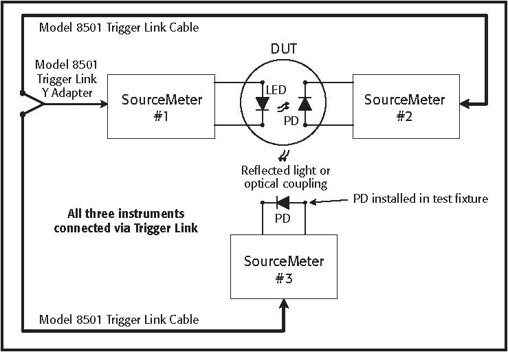
Figure 11. LED with two Photodetector System configuration.
It is possible to synchronize the system by using only Trigger Link on three instruments without external control. Connecting three meters together is easily done with the Model 8505 Trigger Link Y-adapter and two Model 8501 Trigger Link Cables, as shown in Figure 11. The SCPI Trigger Model for the Model 2400 series has two “layers” for control purposes. In this case, one layer is dedicated to each SourceMeter instrument measuring the PDs. The following code lists configuration commands for synchronizing the system shown in Figure 11.
Configuring the Trigger Model
This code listing illustrates the basic Trigger Model commands for performing a 200-point test with three instruments. The actual measurements being performed by the instruments occur at the same time.
|
Send2400_1 (“*RST”) |
‘ Reset SourceMeter #1 |
|
Send2400_1 (“TRIG:CLE”) |
‘ Clear any pending input triggers |
|
Send2400_1 (“arm:coun 200”) |
‘ Perform # points in test |
|
Send2400_1 (“arm:sour tlin”) |
‘ Wait for trigger from 2400 #3 |
|
Send2400_1 (“arm:dir sour”) |
‘ Skip 1st trigger event |
|
Send2400_1 (“arm:outp none”) |
‘ No output triggers from scan |
|
Send2400_1 (“arm:ilin 3”) |
‘ Define arm layer input line |
|
Send2400_1 (“trig:coun 1”) |
‘ Perform one point of test |
Send2400_1 (“trig:sour tlin”) ‘ Trigger using Trigger Link
Send2400_1 (“trig:dir sour”) ‘ Skip first trigger
Send2400_1 (“trig:outp sour”) ‘ Output trigger after source “on”
Send2400_1 (“trig:inp sour”) ‘ Wait for trigger before source
|
Send2400_1 (“trig:ilin 1”) |
‘ Input trigger line |
|
Send2400_1 (“trig:olin 2”) |
‘ Output trigger line |
|
Send2400_1 (“trig:del 0”) |
‘ Set trigger delay before source |
|
Send2400_2 (“*RST”) |
‘ Reset SourceMeter #2 |
|
Send2400_2 (“TRIG:CLE”) |
‘ Clear any pending input triggers |
|
Send2400_2 (“arm:coun 1”) |
‘ Perform only one scan |
Send2400_2 (“arm:sour imm”) ‘ Immediately start scan
Send2400_2 (“arm:dir acc”) ‘ Wait for trigger event (IMM)
Send2400_2 (“arm:outp none”) ‘ No output triggers from scan
Send2400_2 (“trig:coun 200”) ‘ Perform # points in test
Send2400_2 (“trig:sour tlin”) ‘ Trigger using Trigger Link
Send2400_2 (“trig:dir acc”) ‘ Wait for first trigger
Send2400_2 (“trig:inp sour”) ‘ Wait for trigger before source “on”
Send2400_2 (“trig:outp sens”) ‘ Output trigger after measure
|
Send2400_2 (“trig:ilin 2”) |
‘ Input trigger line |
|
Send2400_2 (“trig:olin 1”) |
‘ Output trigger line |
|
Send2400_2 (“trig:del 0”) |
‘ Set trigger delay before source |
|
Send2400_3 (“*RST”) |
‘ Reset SourceMeter #3 |
|
Send2400_3 (“TRIG:CLE”) |
‘ Clear any pending input triggers |
|
Send2400_3 (“arm:coun 1”) |
‘ Perform only one scan |
|
Send2400_3 (“arm:sour imm”) |
‘ Immediately start scan |
|
Send2400_3 (“arm:dir acc”) |
‘ Wait for trigger event (IMM) |
Send2400_3 (“arm:outp none”) ‘ No output triggers from scan
Send2400_3 (“trig:coun 200”) ‘ Perform # points in sweep
Send2400_3 (“trig:sour tlin”) ‘ Trigger using Trigger Link
Send2400_3 (“trig:dir acc”) ‘ Wait for first trigger
Send2400_3 (“trig:inp sour”) ‘ Wait for trigger before source “on”
Send2400_3 (“trig:outp sens”) ‘ Output trigger after measure
Send2400_3 (“trig:ilin 2”) ‘ Input trigger line
Send2400_3 (“trig:olin 3”) ‘ Output trigger line Send2400_3 (“trig:del 0”) ‘ Set trigger delay before source
The SDM cycle’s input and output triggers that were enabled in this code example are summarized in Figure 12. From the initial “INIT” command, the three instruments then trigger each other to complete their measurement operations at virtually the same time. To ensure the measurements occur at the same time, the NPLC, auto zero, and source delay settings should be the same on both PD meters. Also, auto ranging should be disabled for faster execution and synchronization.
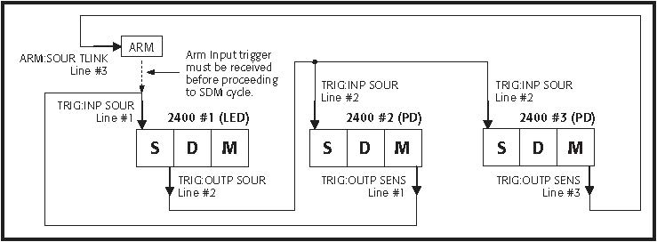
Figure 12. SDM triggers to synchronize three SourceMeter instruments.
Alternative Solutions
Often, the triggering scheme required for a test system is too cumbersome or complex to implement with the SCPI Trigger Model built into the instruments. For total trigger control and synchronization of the system, an external, dedicated trigger controller should be used. If a piece of equipment has input (start-of-test) and output (measurement complete) triggers, then using a trigger controller is fairly straightforward. Trigger control modules function as trigger routers, which issue and wait for triggers as programmed.
Trigger controllers generally become invaluable when a test system is built using equipment from different manufacturers or even products from the same manufacturer with different methods of triggering. The trigger controller takes the guesswork out of learning the nuances involved in operating each piece of instrumentation.
Trigger Controller (Model 2361)
The Model 2361 is a GPIB-based trigger control unit (TCU) with enough independent inputs and outputs to control up to six instruments. It has six outputs and six inputs, all accessed through BNC connectors. The Model 2361 also has an extra digital I/O port with eight inputs and eight outputs for controlling other devices in the test system, in addition to instrument triggering.
Figure 13 illustrates how the system shown in Figure 11 can be redesigned using an external trigger controller. This approach may be desirable because it’s not dependent on the platform architecture of the SourceMeter instruments and can incorporate other instruments easily. As Figure 13 shows, the two SourceMeter instruments originally used to measure the PDs are replaced with Model 6517B Electrometers. The electrometers have built-in voltage sources and provide superior low-current measurement performance.
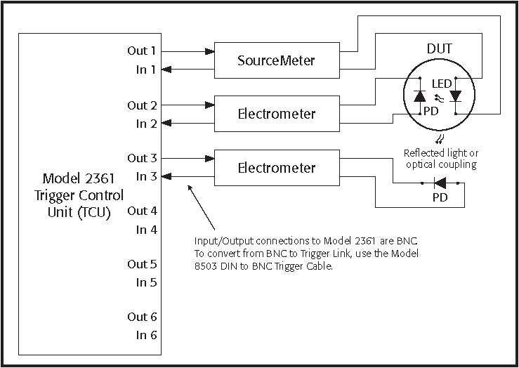
Figure 13. Trigger control performed by Keithley Model 2361 TCU.
Other Trigger Link Components
The following accessories are designed for connecting multiple instruments via the Trigger Link bus.
Model 8501 Standard Trigger Link cable with 8-pin micro DIN connector on both ends. Can be ordered in one- and two-meter lengths.
Model 8502 Adapter box for splitting the six individual trigger lines on the 8-pin micro DIN Trigger Link connector to BNC connectors.
Model 8503 Micro DIN to BNC adapter cable. Useful for converting instruments with only BNC trigger connections to the Trigger Link bus.
Model 8505 Male to 2-female Y-adapter cable. Useful for connecting more than two instruments that have only one Trigger Link connector on the rear panel.
Test System Safety
Many electrical test systems or instruments are capable of measuring or sourcing hazardous voltage and power levels. It is also possible, under single fault conditions (e.g., a programming error or an instrument failure), to output hazardous levels even when the system indicates no hazard is present.
These high voltage and power levels make it essential to protect operators from any of these hazards at all times. Protection methods include:
• Design test fixtures to prevent operator contact with any hazardous circuit.
• Make sure the device under test is fully enclosed to protect the operator from any flying debris. For example, capacitors and semiconductor devices can explode if too much voltage or power is applied.
• Double insulate all electrical connections that an operator could touch. Double insulation ensures the operator is still protected, even if one insulation layer fails.
• Use high-reliability, fail-safe interlock switches to disconnect power sources when a test fixture cover is opened.
• Where possible, use automated handlers so operators do not require access to the inside of the test fixture or have a need to open guards.
• Provide proper training to all users of the system so they understand all potential hazards and know how to protect themselves from injury.
It is the responsibility of the test system designers, integrators, and installers to make sure operator and maintenance personnel protection is in place and effective.
NOTE: The example test programs provided are intended to illustrate the concepts presented in this note. These programs may require modification to accommodate desired test parameters and timing.

